Disadvantages as compared to conventional antennas. Some of their major disadvantages are:. Narrow bandwidth. Low efficiency. Low Gain. Extraneous radiation from feeds and junctions. Poor end fire radiator except tapered slot antennas. Low power handling capacity. I.2 Feed Techniques 1.
- Disadvantages as compared to other conventional antennas. The major disadvantages are. Bandwidth is narrow. Efficiency is low. Less Gain 4. MICROSTRIP PATCH ARRAY ANTENNA Antenna arrays are used to enhance various antenna parameters like bandwidth, directivity, gain, beam width and efficiency. There are a variety of methods to feed the.
- Slot antennas are sometimes called slot radiators. A slot antenna is not the same thing as a slot periodic antenna. A single narrow slot antenna can work on frequencies plus or minus ten percent of their resonant frequency. This is difficult to achieve with array antennas. The longer the slotted antenna, the narrower the beam.
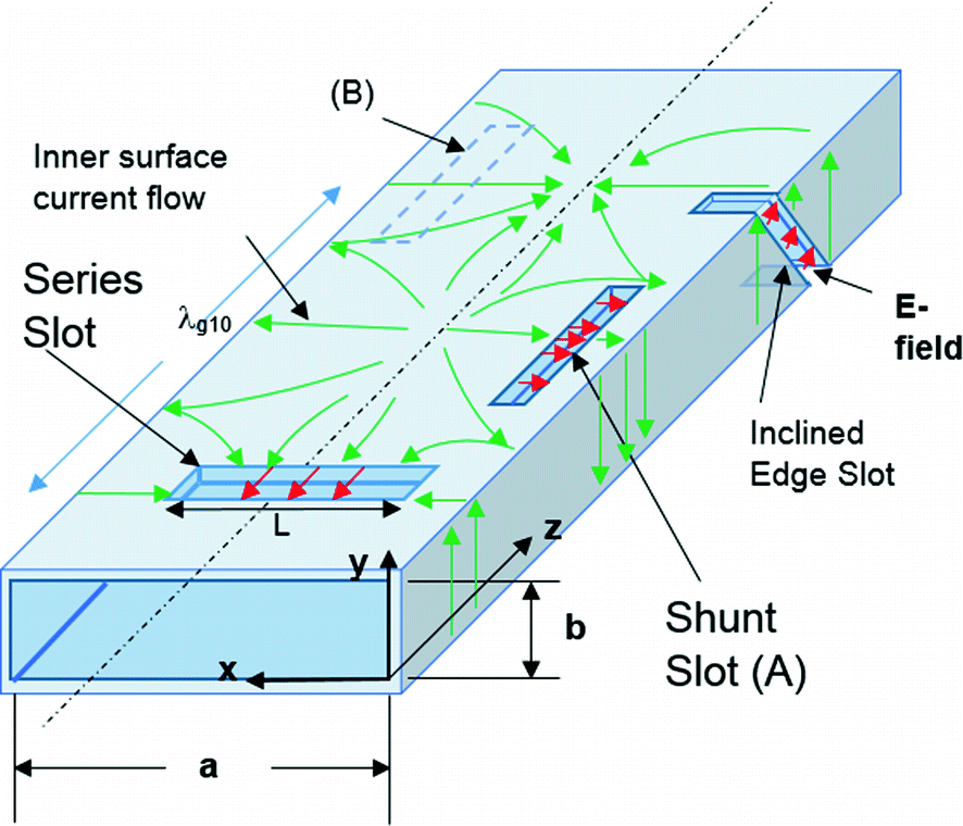
A slot antenna consists of a metal surface, usually a flat plate, with one or more holes or slots cut out. When the plate is driven as an antenna by a driving frequency, the slot radiates electromagnetic waves in a way similar to a dipole antenna. The shape and size of the slot, as well as the driving frequency, determine the radiation pattern. Often the radio waves are provided by a waveguide, and the antenna consists of slots in the waveguide. Slot antennas are usually used at UHF and microwave frequencies, where the waves are usually conducted by waveguide, so a slot in the waveguide makes a simple antenna. They are often found in standard desktop microwave sources used for research purposes. A slot antenna's main advantages are its size, design simplicity, and convenient adaptation to mass production using either waveguide or PC board technology.
An antenna consisting of multiple parallel slots in a waveguide is a widely used array antenna which radiates a narrow fan-shaped beam of microwaves at right angles to the waveguide, with its narrow axis in the plane of the waveguide and its wide axis perpendicular to the waveguide. Multiple slot versions are widely used in radar antennas, particularly marine radar antennas on ships, and for the sector antennas used for cell phone base stations.
Due to Babinet's principle a slot in a waveguide has the same radiation pattern as a driven rod antenna whose rod is the same shape as the slot. This can be used to determine the radiation pattern using calculations for a more conventional antenna.
The slot antenna was invented in 1938 by Alan Blumlein, while working for EMI. He invented it in order to produce a practical type of antenna for VHF television broadcasting that would have horizontal polarization, an omnidirectional horizontal radiation pattern and a narrow vertical radiation pattern.[1][2]
See also[edit]
- Microwave Radiometer (Juno) (has a slot array antenna)
- RIMFAX (radar for Mars rover has slot antenna design)
References[edit]
- ^Blumlein, Alan (1938-03-07), 'Improvements in or relating to high frequency electrical conductors or radiators', British patent no. 515684
- ^Burns, Russell (2000). The life and times of A.D. Blumlein. Institution of Engineering and Technology. ISBN0-85296-773-X.
External links[edit]
- 'Slot Antennas'. Antenna Theory.
Advantages And Disadvantages Of Television
- Antenna Theory Tutorial
- Antenna Basic Terms
- Types of Antennas
- Antenna Arrays
- Wave Propagation
- Antenna Theory Useful Resources
- Selected Reading

A Collinear array consists of two or more half-wave dipoles, which are placed end to end. These antennas are placed on a common line or axis, being parallel or collinear.
The maximum radiation in these arrays is broad side and perpendicular to the line of array. These arrays are also called as broad cast or Omni-directional arrays.

Frequency range
The frequency range in which the collinear array antennas operate is around 30 MHz to 3GHz which belong to the VHF and UHF bands.
Construction of Array
These collinear arrays are uni-directional antennas having high gain. The main purpose of this array is to increase the power radiated and to provide high directional beam, by avoiding power loss in other directions.
The above images show the pictures of collinear arrays. In figure 1, it is seen that collinear array is formed using folded dipoles, while in figure 2, the collinear array is formed by normal dipoles. Both types are half-wave dipoles used commonly.
Radiation Pattern
The radiation pattern of these collinear arrays is similar to that of a single dipole, but the array pattern of increasing number of dipoles, makes the difference.
The radiation pattern of collinear array when made using two elements, three elements and four elements respectively are shown in the figure given above.
The broad side array also has the same pattern, in which the direction of maximum radiation is perpendicular to the line of antenna.
Advantages
The following are the advantages of collinear array antennas −
- Use of array reduces the broad ends and increases the directivity
- Minor lobes are minimised
- Wastage of power is reduced
Disadvantages
The following are the disadvantages of collinear array antennas −
- Displacement of these antennas is a difficult task
- Used only in outdoor areas
Applications
The following are the applications of collinear array antennas −
Advantage & Disadvantage Of Computer
- Used for VHF and UHF bands
- Used in two-way communications
- Used also for broadcasting purposes